fp-arduino
Arduino IDE
You must have a USB-A port on your laptop, or a USB-A adapter.
The Arduino board must be connected to your laptop by USB for power and to upload your program. If your computer does not have a USB-A port, you will need to obtain an adapter. The kit does not contain an adapter.
Install the Arduino IDE
The course staff will support the official Arduino IDE only. While you are permitted to use a plugin for Visual Studio, the online Arduino IDE, or some other IDE solution, the staff will only assist with the official Arduino IDE.
Everyone on the team should follow the steps below to install the Arduino IDE and create a sketch with the starter file.
-
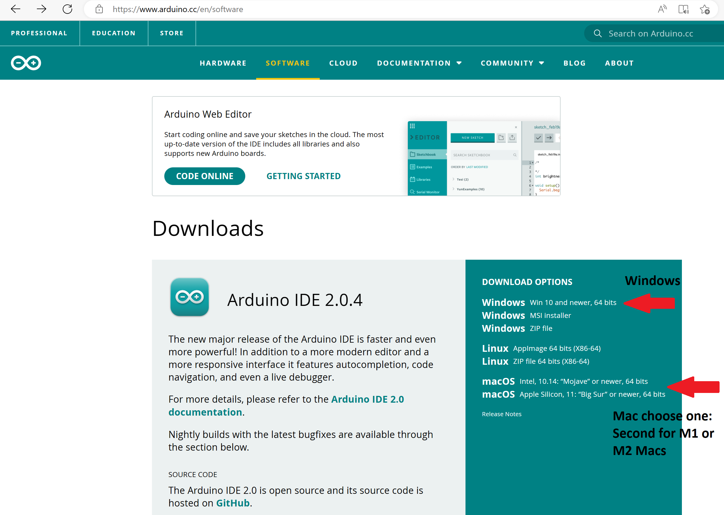
Go to https://www.arduino.cc/ and select Software. Then select the version based on your computer. Windows users who are not sure which option to choose can select the top option. Note that the Arduino IDE version number may be different than in the picture below.
-
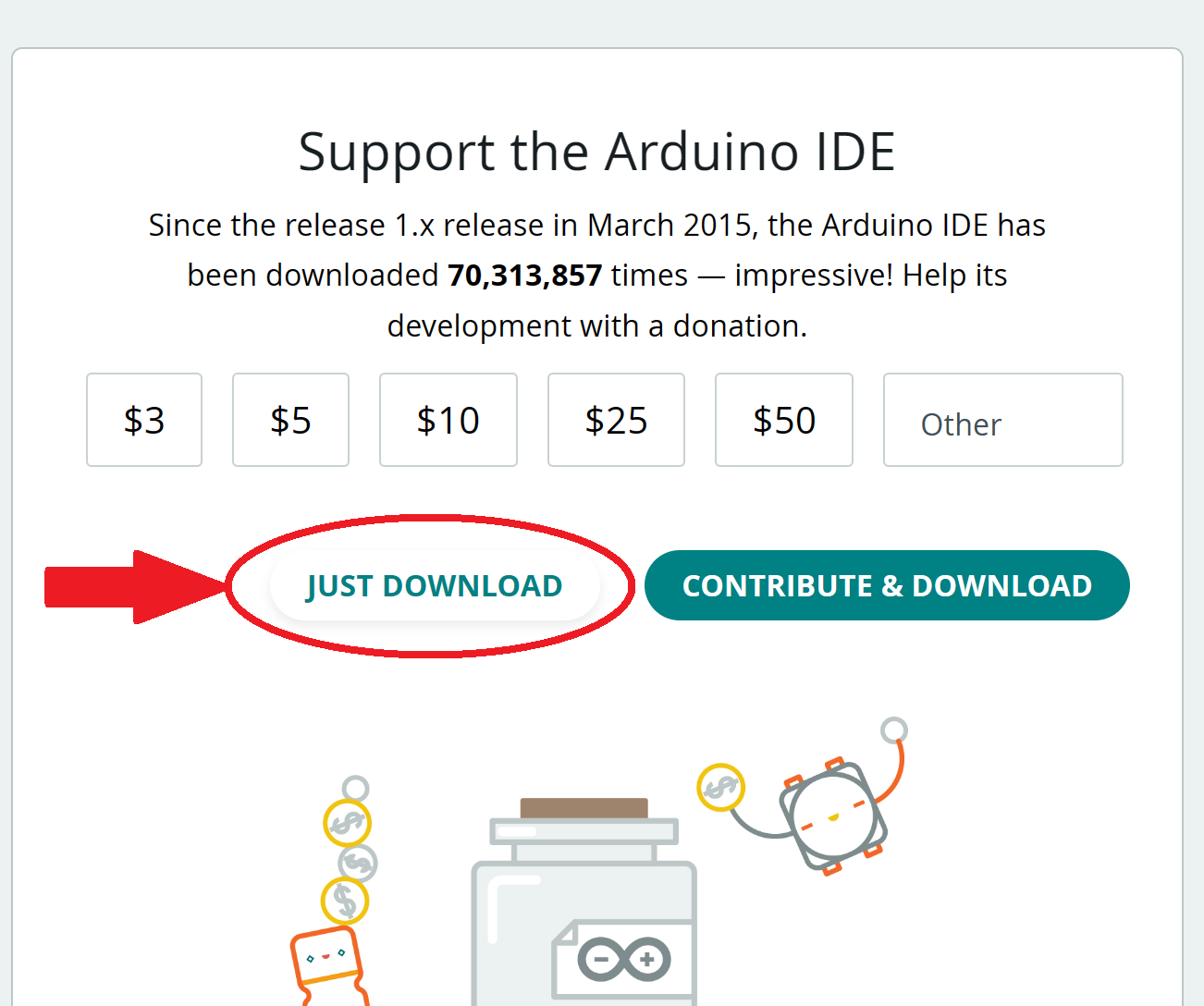
Select “Just Download” and once the download completes (you will have to do this twice), run the installer file.

-
Follow the instructions in the installer. There will be several notifications from Windows or MacOS about installing additional components and allowing access. Select Allow access or Install for these. They may include Adafruit Industries, Ardunio, and Newtork Access.
-
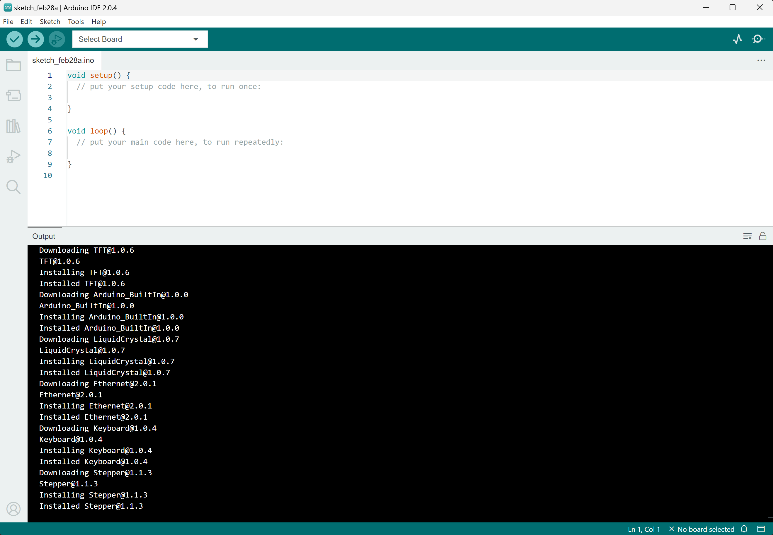
Once installation is complete, run the Arduino IDE. You should see something like this.
-
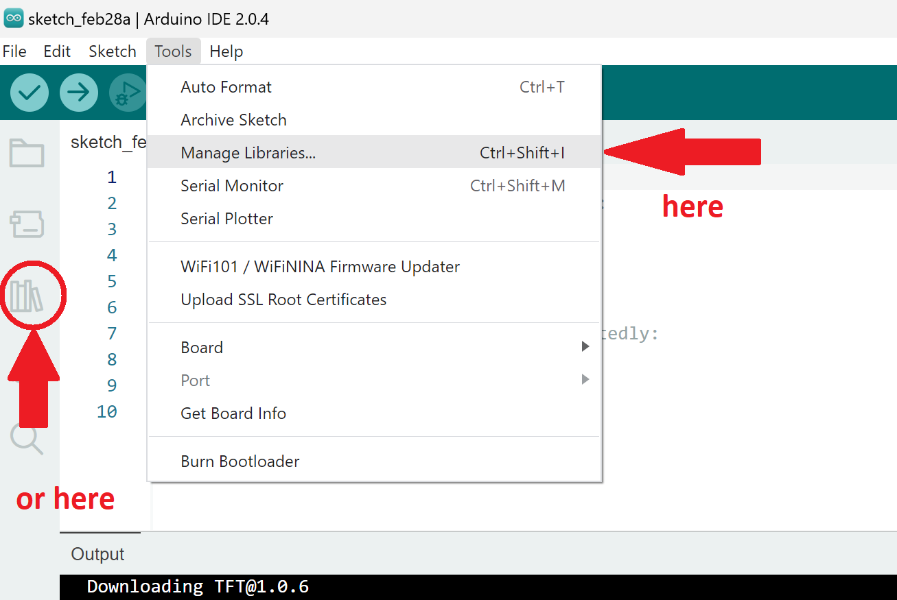
To install the Adafruit libraries necessary for the project, select Tools -> Manage Libraries…
-
There are two libraries to install. First, type
adafruit gfxinto the search box. Select INSTALL for the Adafruit GFX Library by Adafruit.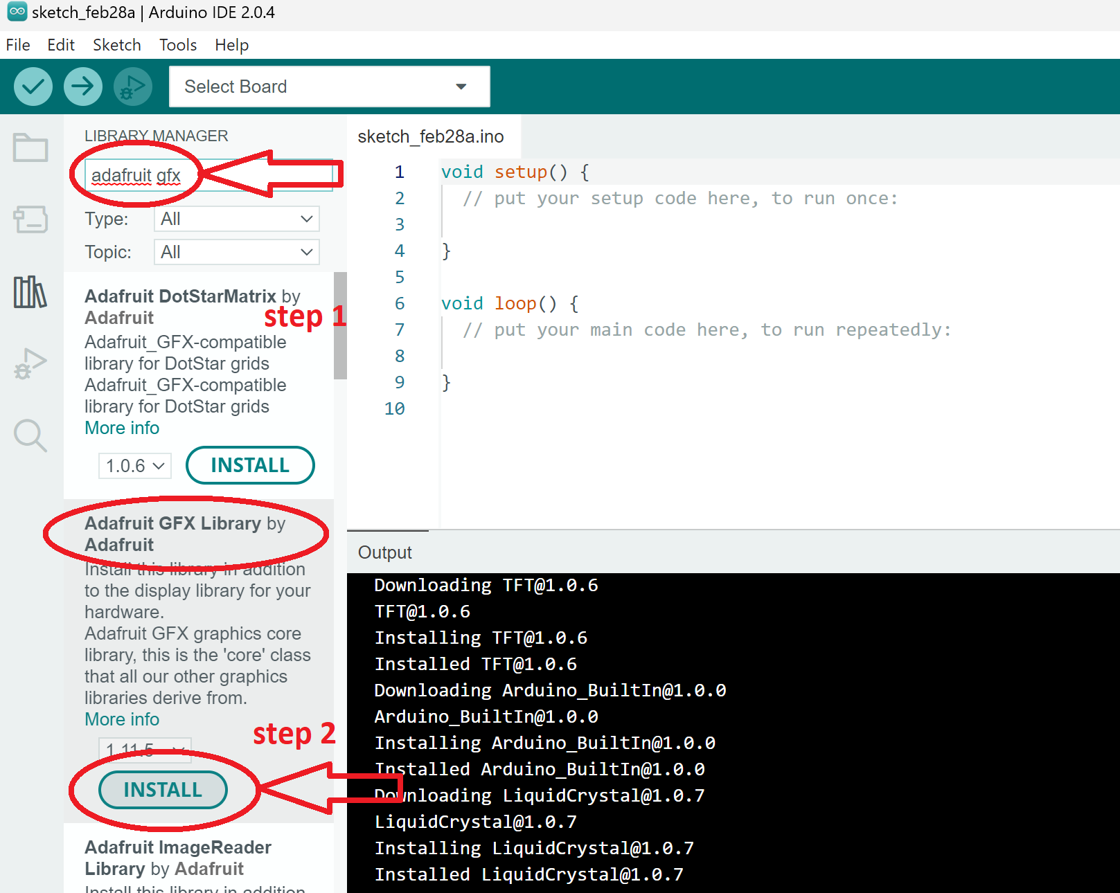
-
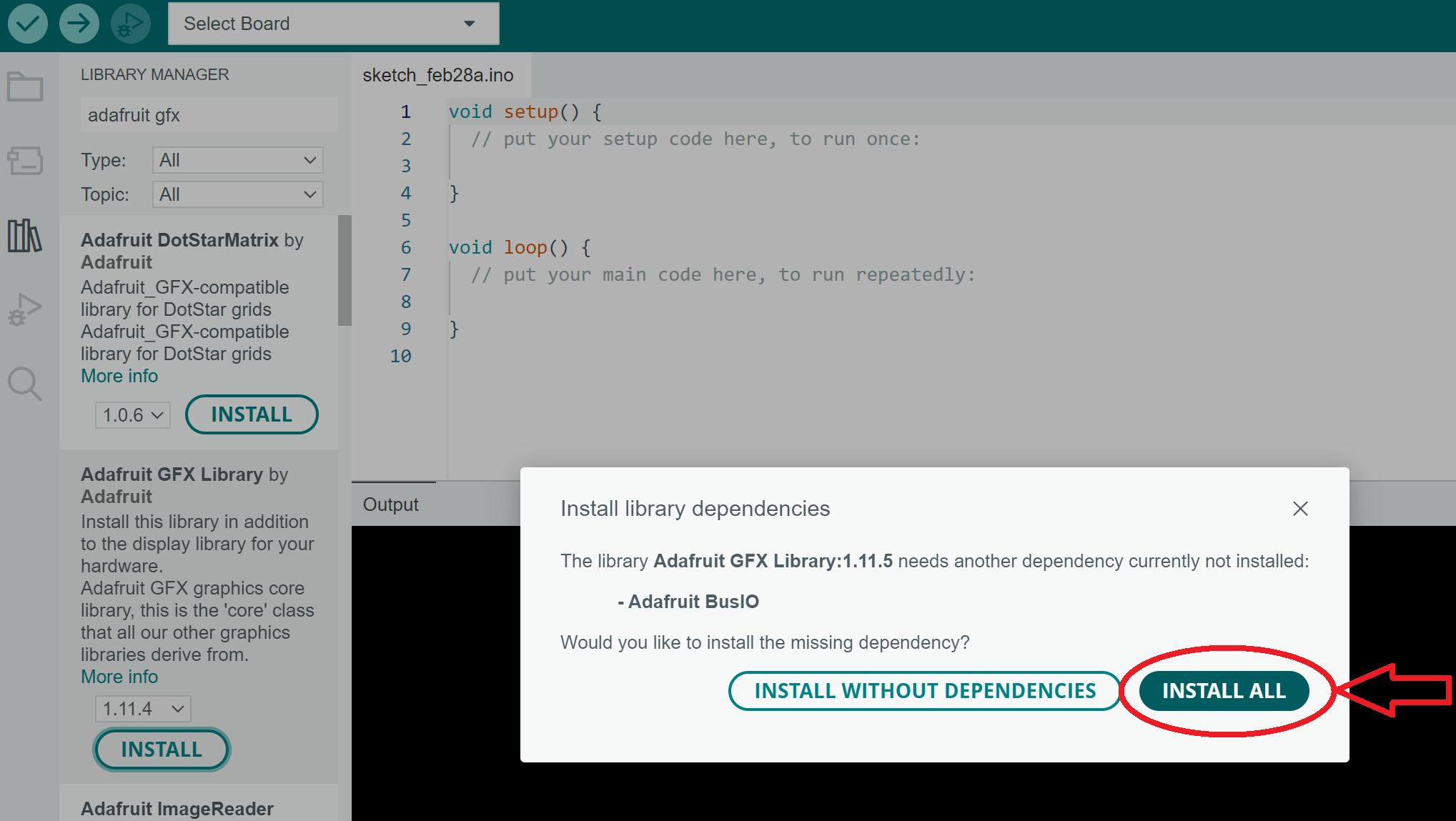
Select INSTALL ALL.
-
Go back to the search box for managing libraries and enter
rgb matrix panel. Select INSTALL for the RGB matrix Panel by Adafruit.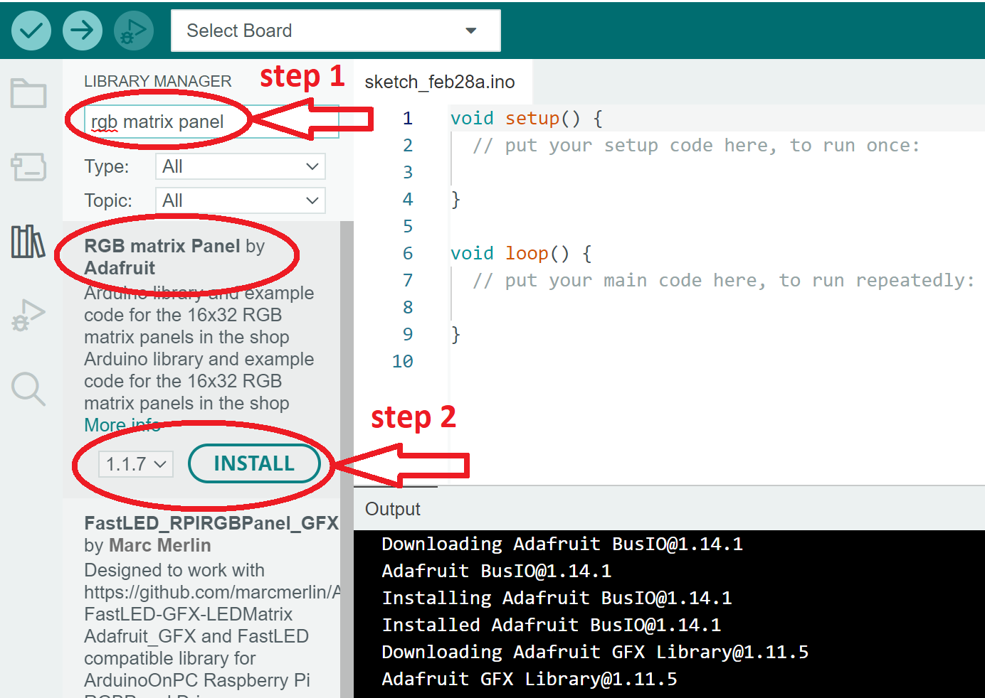
-
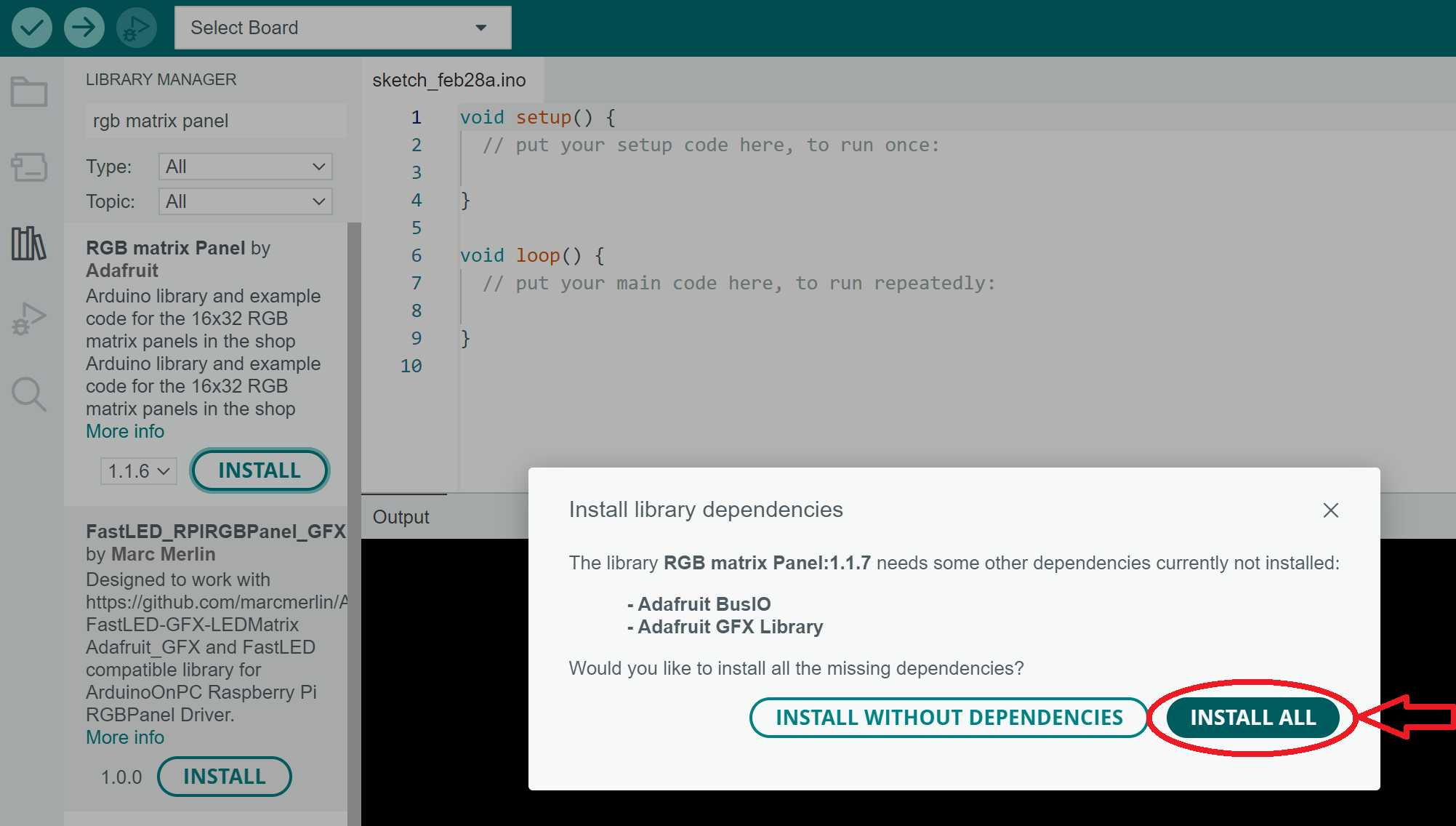
Select INSTALL ALL.
-
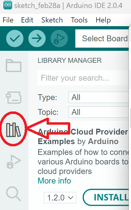
Installation of the Arduino IDE and required libraries is now complete. You can close the Library Manager window by selecting the small books icon on the left.
Create a Sketch with the Starter File
Arduino programs are called sketches. For the Core, you will only need one file.
-
Start by downloading the starter files here. There is only one file in the starter-files,
space_invaders.inoin the folder space_invaders. -
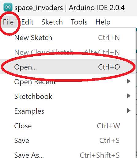
In the Arduino IDE, from the top left corner, select File -> Open.
-
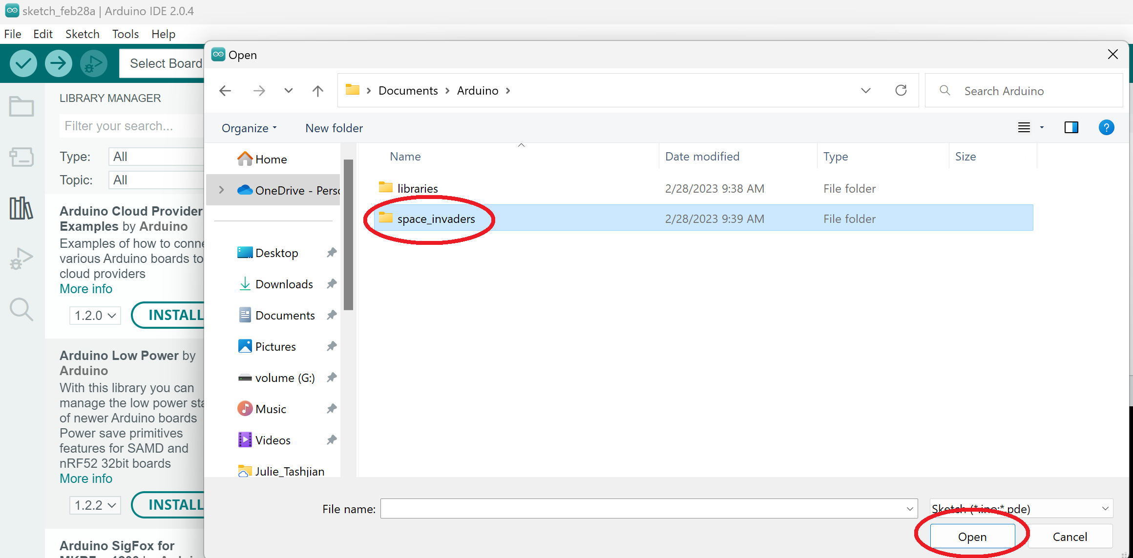
Navigate to where you saved your starter file folder. Note: you can copy the space_invaders folder to your Arduino folder, shown here. Wherever your space_invaders.ino file is located, it must be within a folder named space_invaders. The Arduino IDE requires any sketch to be within a folder of the same name.
-
Select
space_invaders.inoand Open.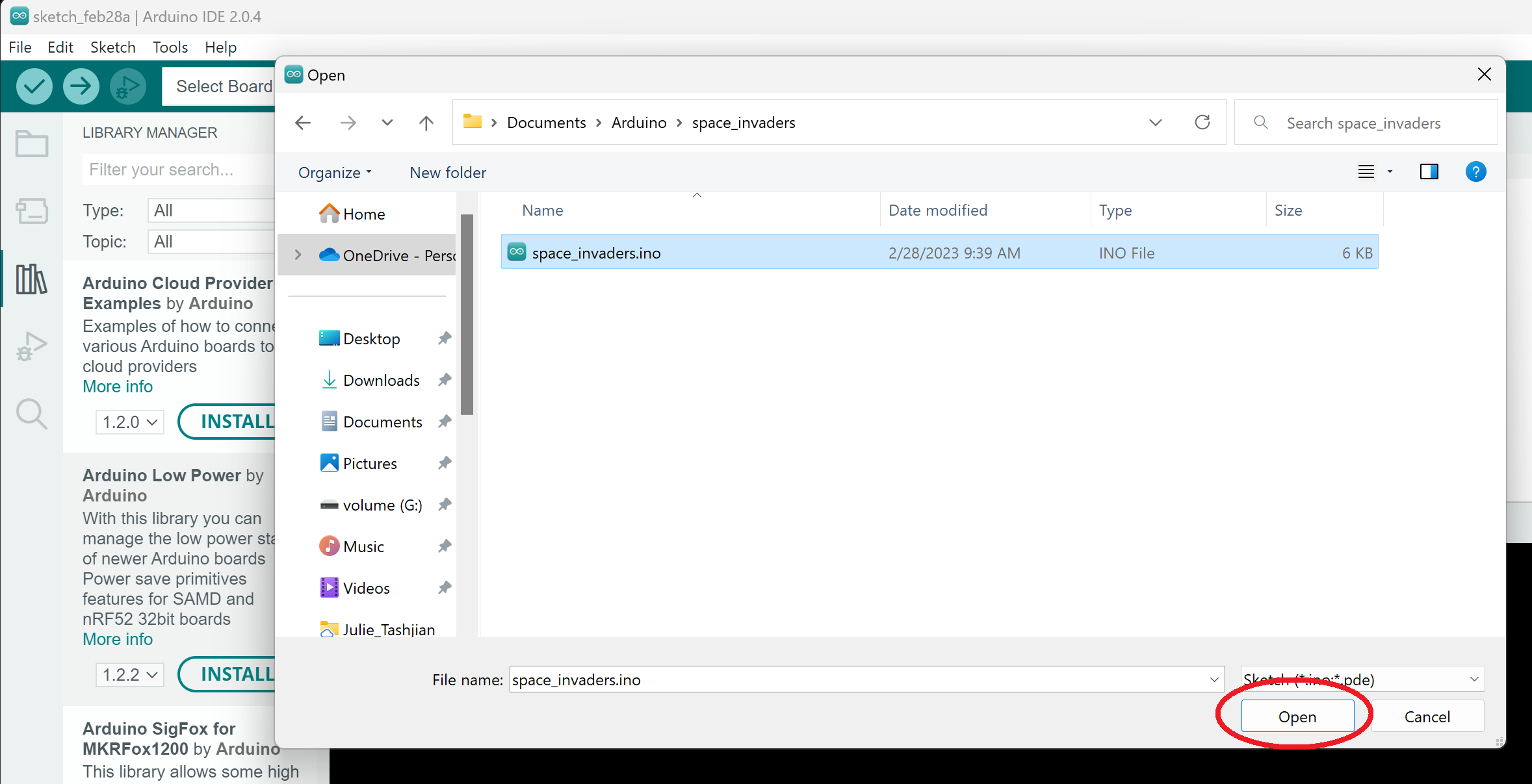
-
You should see another Arduino IDE window, with the starter code visible. You may close the other Arduino IDE window, leaving the
space_invaderswindow open.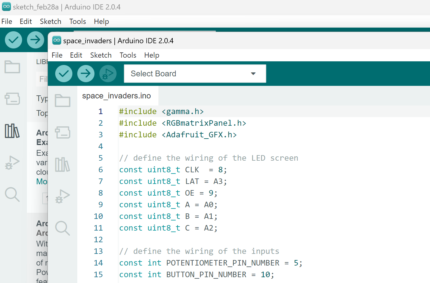
-
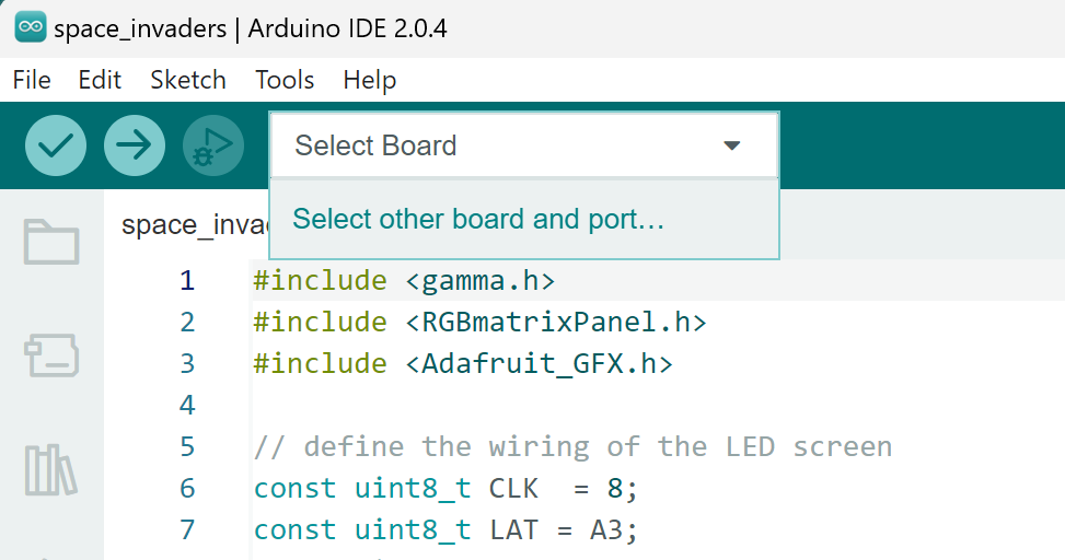
To compile and run the code, you will need to select the Arduino Uno board. Start by clicking on Select Board, then Select other board and port.
-
Type
unoin the seach box and select Arduino Uno.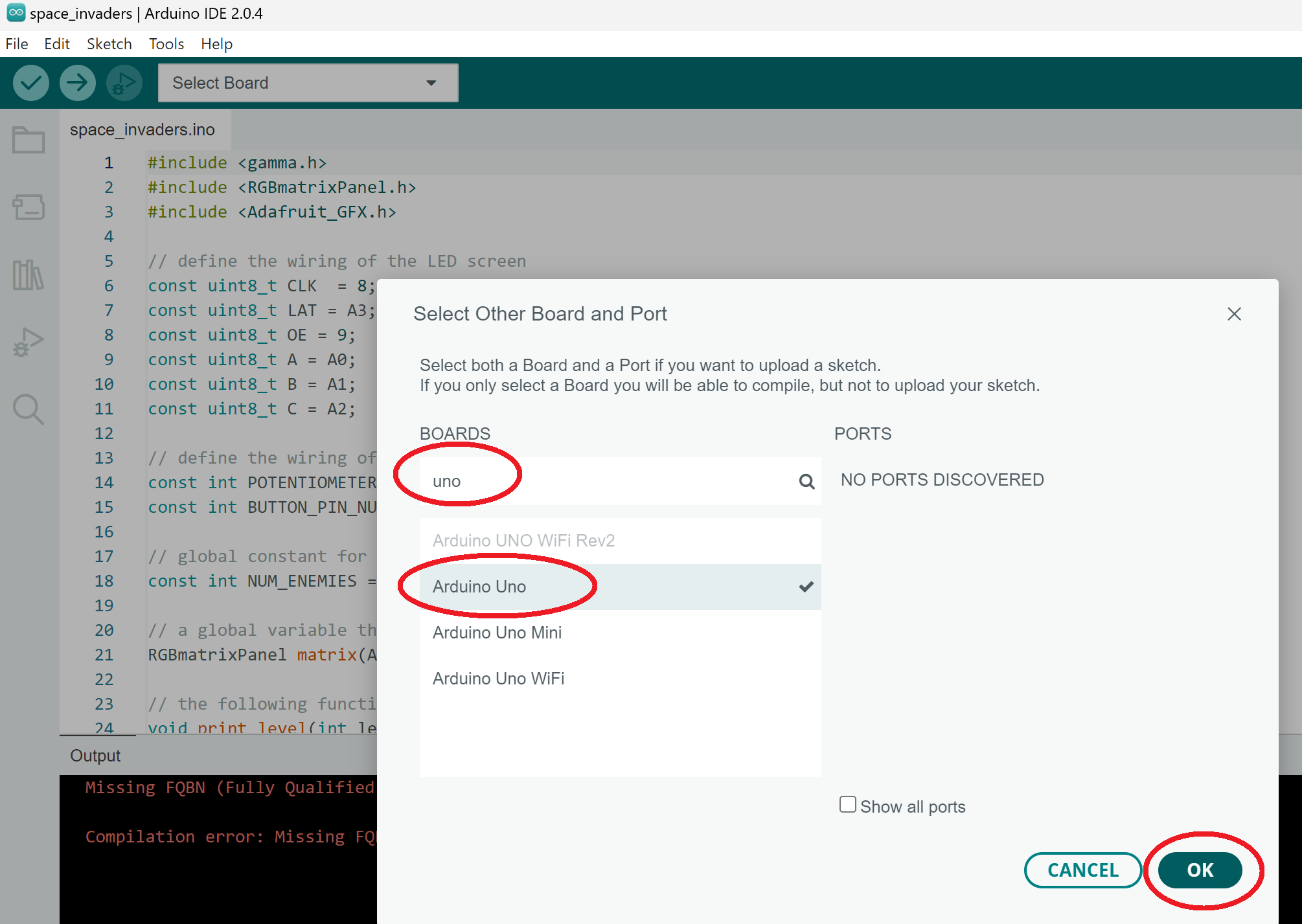
-
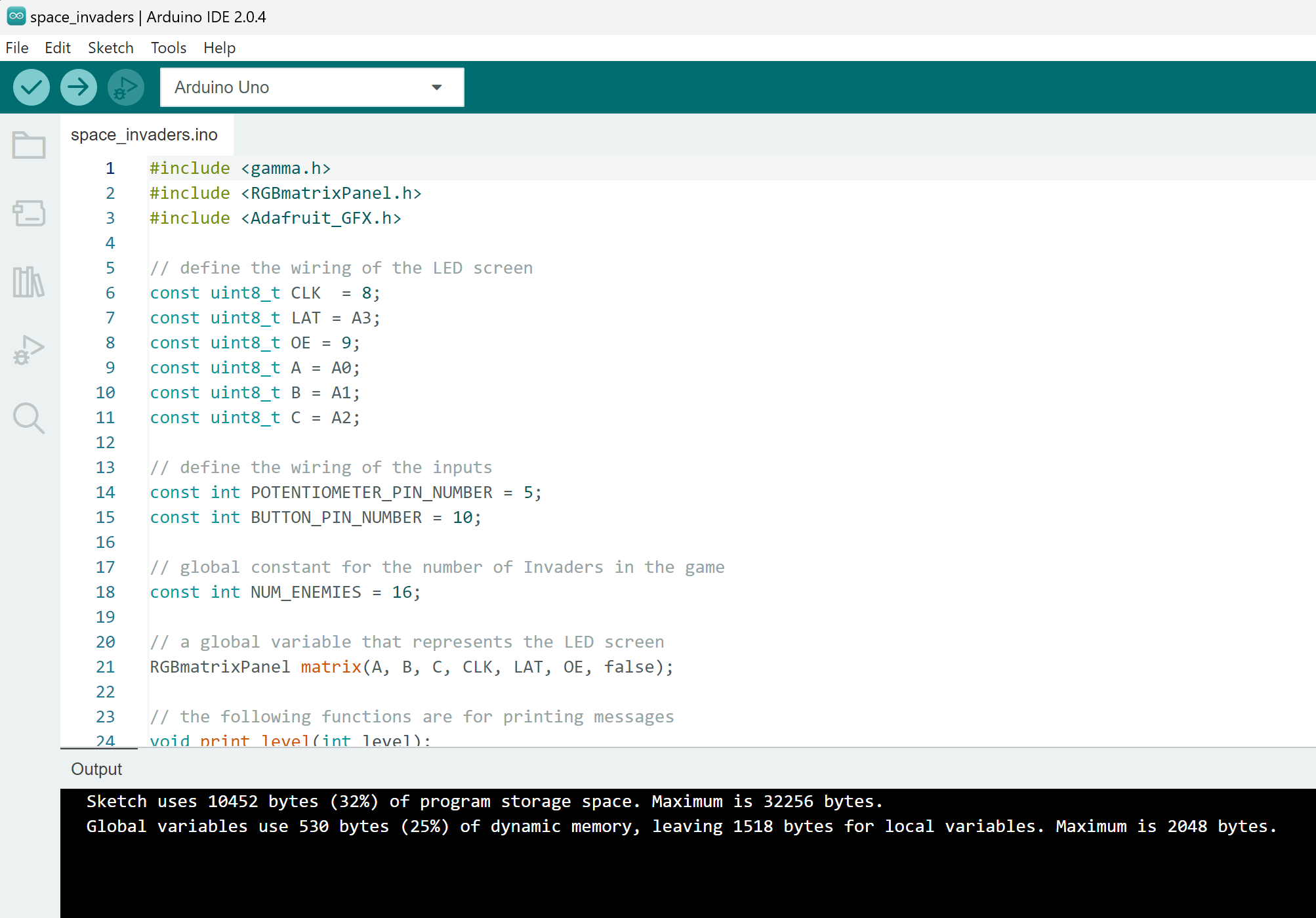
Select the check mark in the upper right corner to compile the starter file - called Verify in the Arduino IDE. After it compiles successfully, you should see a message at the bottom similar to what is shown below.
-
The setup of the starter code is now complete. Move on to the next section to connect your Arduino board to your laptop and upload the sketch to the board for testing.
Uploading a Sketch to the Arduino
After installing the Arduino IDE and creating a sketch with the starter file, you will need to upload your sketch to test all of your work.
When you connect the Arduino to a USB port on your computer, a small light on the Arduino should turn on.
If, after the board is connected and a short pause, there are no lights then disconnect the board from the USB cable. It is possible, especially after reconnecting wires that have been disconnected, to incorrectly wire the kit. This can cause the Arduino board to be permenently damaged, and the board can become hot enough to burn on touch. If you have any concerns, come to office hours so staff can inspect your kit.
-
Plug the Arduino into a USB port on your computer. You should see the small light on the board turn on when connected.
-
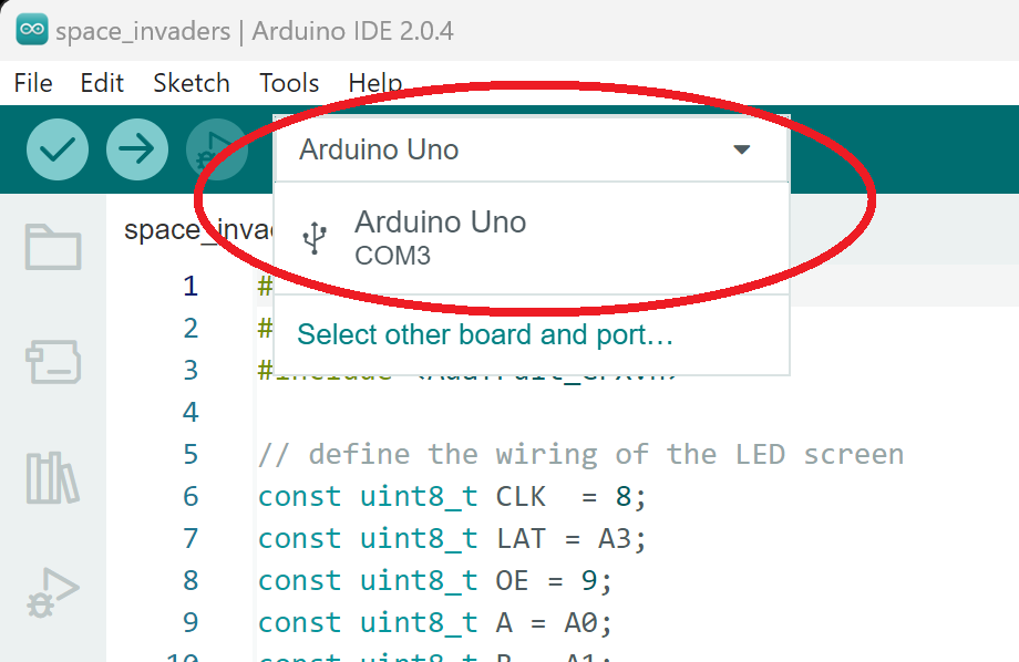
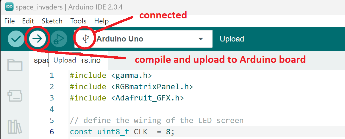
The Arduino IDE should automatically detect the board connection. You can verify this, or select the correct port, by selecting the Arduino Uno from the top of the IDE. Note that your port name or number may be different than what is shown below. After selecting the port, you should see a small icon next to the name Arduino Uno
-
Select Upload, the arrow icon near the top.
-
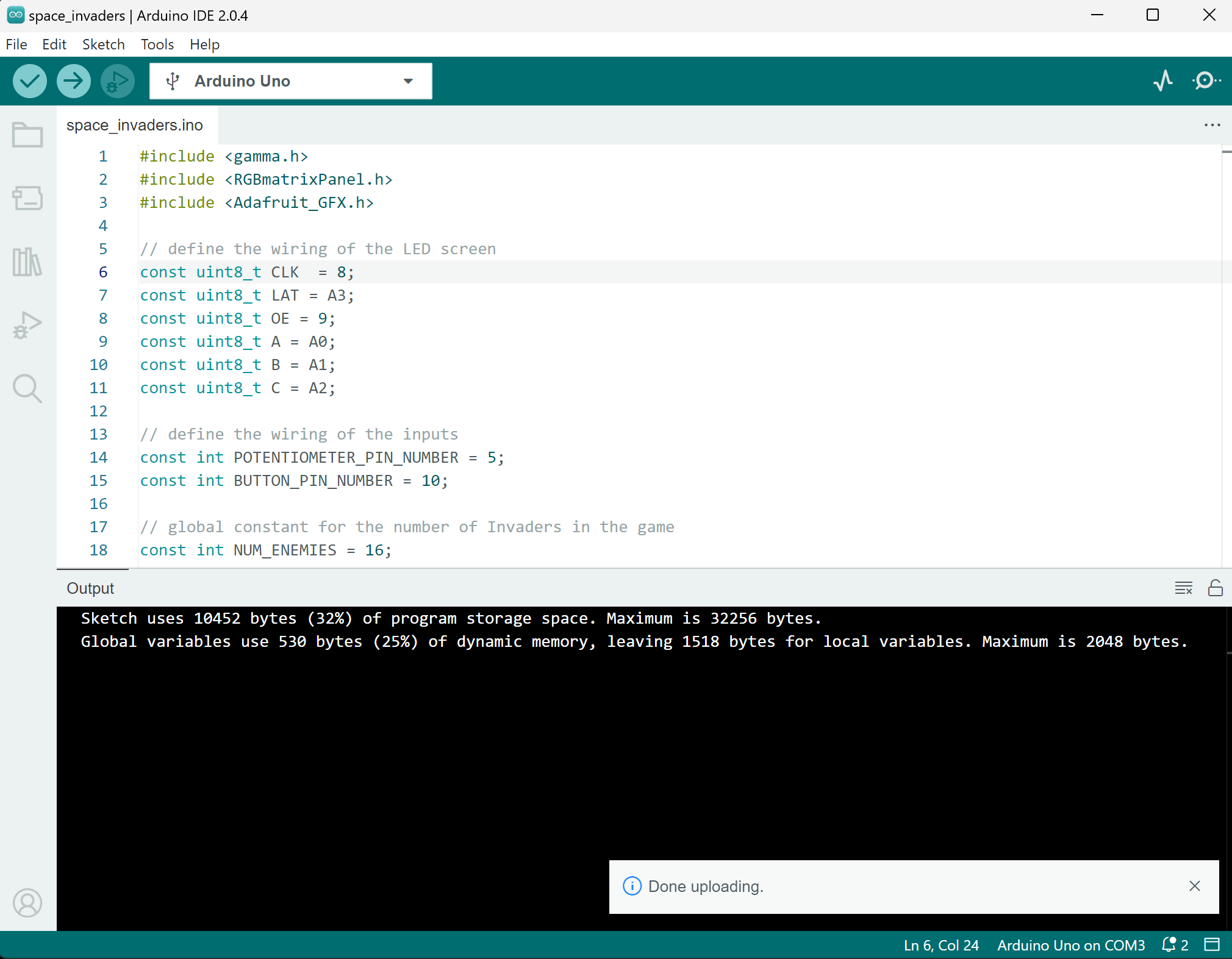
The small lights on the Arduino board will briefly blink while uploading. After the upload is complete, a small message should be visible for a short time in the lower right corner of the Arduino IDE showing Done uploading.
-
Uploading the starter file to the Arduino is complete. Nothing will be displayed on the RGB LED panel as there are no statements in the starter file that turn on any of the pixels. Proceed to the next section to turn on your first pixel on the RGB LED matrix panel.
Light One Pixel
To get started on the project, the first task will be to light a single pixel on the LED display. Many things you display on the screen for the Core, and very likely the Reach, will be accomplished by setting individual pixels to a specific color. There are functions for displaying text. The Invaders, player, and cannonballs will be displayed by lighting pixels on the screen.
You can learn more about how an Arduino sketch works in the specification. The steps below show the statements to display one pixel on the LED display.
Note: There will only be one file for the Core. All class member function definitions are within the class definitions.
-
There are many
constglobal variables you will use for the project. There are also non-const gloabal variables you will use, includinggameandmatrix. For this project you may, and will, use gloabal variables. -
There is a complete
Colorclass for you to use, and severalColorglobal variables that will correspond to the colors in the specification.
const Color BLACK(0, 0, 0);
const Color RED(4, 0, 0);
- Whenever your program displays anything to the LED display, you must use the
matrixvariable declared near the top of the program.// a global variable that represents the LED screen RGBmatrixPanel matrix(A, B, C, CLK, LAT, OE, false);
- Find the Game class and the update function.
// advances the game simulation one step and renders the graphics // see spec for details of game // Modifies: global variable matrix void update(int potentiometer_value, bool button_pressed) { } - Add the following statement to the Game class function update.
// advances the game simulation one step and renders the graphics // see spec for details of game // Modifies: global variable matrix void update(int potentiometer_value, bool button_pressed) { // temporary statement to test drawing a pixel to the LED display // First argument - x coordinate // Second argument - y coordinate // Third argument - Color converted to the format required by the drawPixel functiuon matrix.drawPixel(4, 6, RED.to_333()); } - Upload the sketch to the Ardino board. After a brief delay, you should see a pixel on the board light red. Note: this will also show you which corner of the board is at (0, 0), and the orientation of the board - which argument to draw pixel represents which dimension on the LED display.