fp-arduino
EECS 183 Final Project: Arduino
Core Due Friday, April 10, 8 pm - submit your space_invaders.ino file here
Reach Due Tuesday, April 21, 8 pm - submit your reach file(s) here after reach starts
Office hours times and locations may change for the final project. Check the Office Hours details here
This project involves using the Arduino micro-controller to link two sensors to an LED screen, so that you can play Space Invaders. The goal of this project is for you to:
- Create something new of your own design.
- Gain experience working with hardware, including circuits.
- Understand the basics of how software can control hardware, both input (a potentiometer and a button) and output (an LED screen)
- Solidify the concepts you’ve learned in EECS 183, including functions, branches, loops, arrays, and classes
- Use these concepts in a comprehensive project
- Start moving beyond simply writing code to designing programs
- Have fun!
This project does not use an autograder to determine grades.
The project is graded by staff playing the game that your team creates. An autograder is not used to grade this project. Grading rubrics are shown in the specification. All grading will be done after the submission deadline.
- Pros - unlike the autograder, people are less pedantic and are not as thorough at finding bugs. The grading is less stringent since we just play your game.
- Cons - you will have to check the rubric to know you have achieved what is asked. Staff will not pregrade before the deadline.
This project (Arduino C++) is limited to a maximum of 25 teams.
Please reserve your team space and hardware kit by completing the reservation steps.
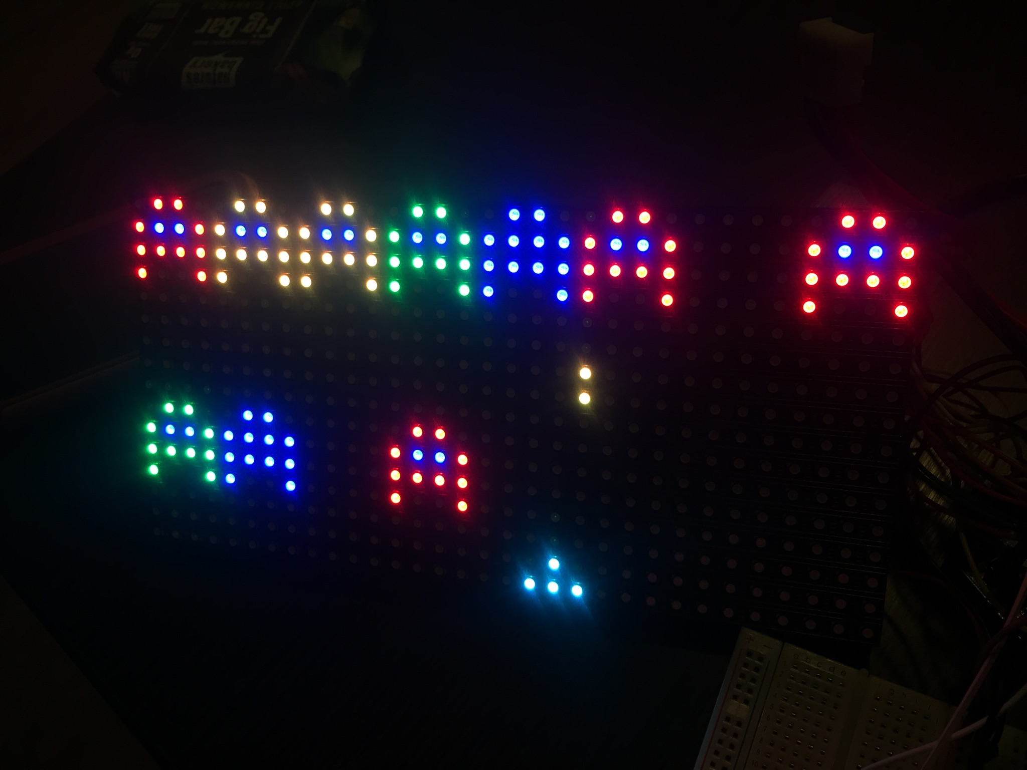
Here’s a picture of what your Core product will look like:
Here’s a brief demo of the project:
This project will be limited to the first 25 teams to request this project. Your team MUST submit a reservation request using the Arduino Team Sign-Up form. Only one sign up per team, please. Also note that, should the limit of 25 teams be reached before this time, the sign up form will close and your team will not be able to select this project.
For the Reach, you will be able to implement a game of your choice. Because of this flexibility, the Reach will be graded by hand at the Showcase. There are no autograders for either the Core or the Reach, so if you prefer to have feedback from the autograder, you may wish to choose a different final project.
Your team will be provided all of the hardware to complete the project. We will notify teams who sign up about where you can pick up your hardware kit.
Here are the pages of this specification, for quick reference while you are coding the project:
Table of Contents
- Core
- Getting Started
- Hints
- Reach
- Submission and Grading
- Troubleshooting
- Office Hours
- Support Staff
- References
Core
The core part of this project is for you to implement a clone of Space Invaders, an early arcade game and a key part of video game history. We chose this game so that it is approachable for beginning programmers and game developers while fitting the micro Arcade platform well.
Hardware Overview
Your team will be provided with the following necessary hardware
- 1 Arduino Uno
- 1 Adafruit 16x32 RGB Matrix Panel
- 1 breadboard
- 2 potentiometers
- 2 buttons
- 1 flat ribbon cable
- 1 USB cable
- 1 5V power converter
- wires
- resistors
- 1 box
The Arduino
The Arduino is a single-board microcontroller, essentially a tiny computing platform for creating interactive projects. The Arduino language is based on C/C++ and is very easy to learn. Libraries are available for all types of displays you will use, and I/O in general is easy to program. Arduino uses its own IDE, and you are expected to use it. You can download it at the Arduino website.
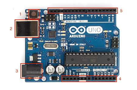
If you orient your Arduino to match the picture above, you can see the main components of the Arduino you will be using. Going counter-clockwise from the top left:
- On the top left corner, there’s a button that restarts the Arduino.
- Just below that button is a USB port, that allows you to upload code to the Arduino.
- On the bottom left corner, there’s 5V power connector. You won’t need to use this, as we will be powering the Arduino by USB.
- Along the lower edge are a series of pins, which connect the Arduino to inputs and outputs. If you look closely, you will see that some pins provide power, while others get analog input (like the potentiometer) and output (like telling the LED screen which rows to light up)
- Along the upper edge, there’s another series of pins. These handle digital input (like the button) and output (like the color of the LEDs).
The Breadboard
The way you will connect the Arduino to its inputs and outputs with through a breadboard. They look like this:
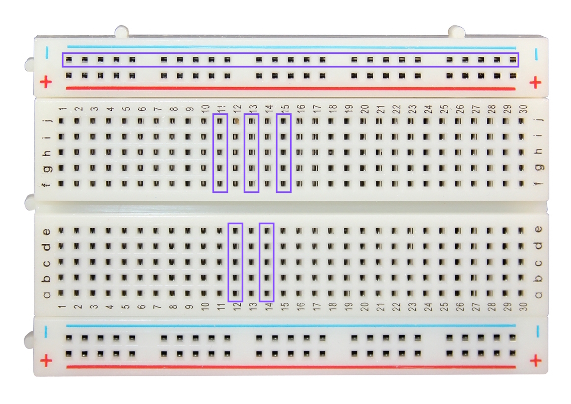
Breadboards let you create circuits by providing an easy way to wire things together. Inside the breadboard, there’s a piece of metal that connects every numbered row, so all wires plugged into that row would share the same voltage/signal. Additionally, the column of holes on the side also share a connection. The colored lines indicate that these holes are usually used for power and ground (red for power, blue for ground) - any electronic circuit needs to have some connection between power and ground to work. For example, in the picture above, all the holes inside a purple rectangle share a connection. For this project, we will mostly be using the power and ground holes on the breadboard.
The Inputs
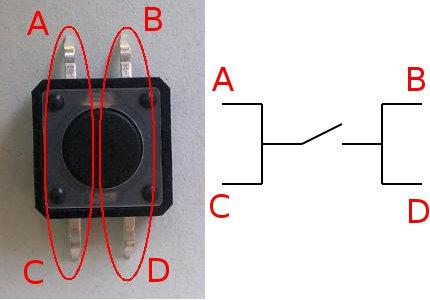
There will be two inputs to your game: a potentiometer and a button. A button is really just a switch - when you press the button, it completes a circuit and changes the voltage, which is how the Arduino knows you pressed the button. For the curious, electrically, it looks like this:
A potentiometer is a much more complicated piece of hardware than a button. If you want to find out more, take a look at the Wikipedia article.
The Output
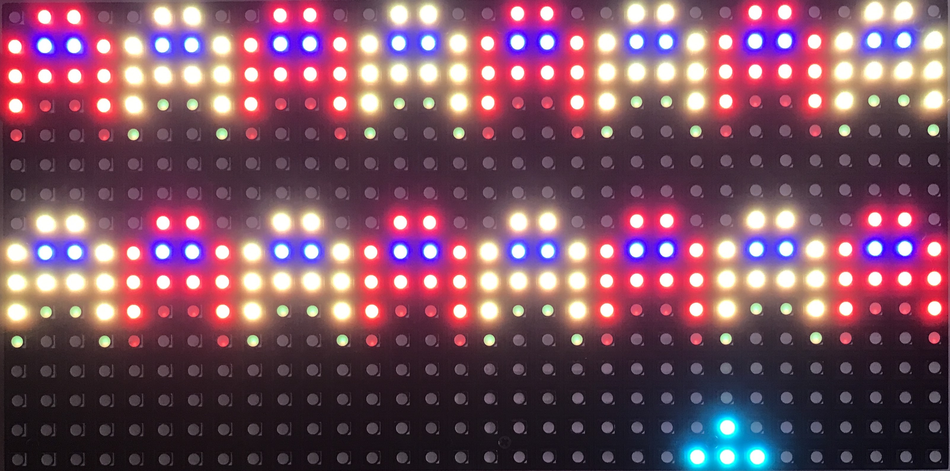
We are using the Adafruit 32x16 LED screen. The front of it looks like this (when it’s lit up):
 Level 2 - note how the bottom row of invaders move while the top row waits.
Each of those bright, little dots is an LED (Light Emitting Diode). We can separately set the amount of red, green, and blue light that comes out of each one. If they’re all on, the LED will be white, and if they’re all off the LED will be black.
On the back, there are three main connectors. Make sure the board says “IN” or “INPUT” and “OUT” or “OUTPUT” near the correct connectors:
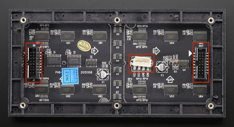
- On the left is the input connector. We will be connecting this to the Arduino via the breadboard, some wires, and a flat ribbon cable.
- In the middle is the power connector. We will be connecting this to the power converter.
- On the right is the output connector. We will not be using this connector in this project.
Returning Hardware
At the end of the showcase, you must return all components that you have checked out from the class. If any component is broken, or if it is not returned at the end of the showcase, you must pay to replace that component. You will not receive your grades for the semester until you have paid.
Software Overview
Your team will be provided with the following necessary software:
- A starter sketch file including the minimal set of functions necessary for the Core project.
- Two libraries for using the LED screen.
Additionally, you will need to install:
- The Arduino IDE
Space Invaders
The goal of this game is to kill all invaders by shooting them, before they can move past you or kill you in turn. You will control a cannon through a potentiometer and a button; the potentiometer controls where you cannon points, while the button fires the cannon.
Every game begins the same way:
- Before the game starts, before a level starts (including when a player dies), display “Lives:
<number of lives>”. - Before the game starts, before a level starts (including when a player dies), display “Level:
<level number>”. - The invaders are then array-ed on the top of the screen; the game begins.
- If an invader’s strength is reduced to 0, it dies and disappears from the screen.
- If an invader touches the player’s cannon, the player dies (and loses a life).
- If an invader reaches the bottom of the board, the player loses a life.
- If all invaders are killed, the next level is loaded.
- The game continues until the player has died three times. Display “Game Over” when this happens.
The initial layout and the strength of the invaders depends on the level. All levels have at most 16 invaders, laid out in two rows of 8.
-
On Level 1, only 8 invaders are present on the top of row, all with strength 1:
1 1 1 1 1 1 1 1 -
On Level 2, 16 invaders are present in two rows, with strengths specified as follows:
1 2 1 2 1 2 1 2 2 1 2 1 2 1 2 1 -
On Level 3, 16 invaders are present in two rows, with strengths specified as follows:
1 2 3 4 5 1 2 3 4 5 1 2 3 4 5 1 -
On Level 4, 16 invaders are present in two rows, with strengths specified as follows:
5 4 5 4 5 4 5 4 2 3 2 3 2 3 2 3 -
On Level 5 and after, the 16 invaders will have randomly chosen strengths. This means level 5 and every level onwards should be different each time it is played (levels should be different every time we play them, do NOT create a set of levels to cycle through). See the Arduino Reference page on the random() and randomSeed() functions to see how to approach this. Note: for the randomseed example you should not use analog read of 0, but instead 4 as there is no wire connected to analog 4.
Graphics
The player’s cannon is drawn as four LEDs, 3 on the bottom and one on top in the middle. The player is always aquamarine in color.
 *
***
The invaders are drawn with 12 LEDs each:
 ##
#**#
####
#  #
The LEDs marked with # change in color depending on the strength of the invader, while the LEDs marked with * are always BLUE. The invaders are colored roughly according to a rainbow:
- Strength 1: RED
- Strength 2: ORANGE
- Strength 3: YELLOW
- Strength 4: GREEN
- Strength 5: BLUE
- Strength 6: PURPLE
- Strength 7: WHITE
Finally, the cannonball fired by the player takes two LEDs, vertically on top of each other. It is always ORANGE.
*
*
Game Dynamics
The player is controlled by the potentiometer, and when the button is pressed, a cannonball should shoot out from the top middle LED. The cannon should be able to shoot from any column of the board; this means that the base of your cannon should be able to move one pixel off the edge of the screen, with the barrel appearing on the edge. When you shoot, the shot should be visible until you reach a creature or until it moves off of the top of the board. Both the cannonball and the invader should disappear if the ball would move on top of the invader. Finally the bottom row of invaders should move down by one LED every few seconds. Only once the bottom row of invaders is completely destroyed, the top row of invaders should start moving down. If an invader overlaps with the player, then the player loses a life. The game continues until the player has lost all three lives. It is up to you what you want to do after displaying “Game Over”. You can either restart the game or keep displaying “Game Over”.
Given this description, the key part of your code will need to do the following:
- Update the position of the player based on the value of the potentiometer
- Update the position of the cannonball, including detecting if a new cannonball is being fired
- Update the position of each invader
- The top row of invaders only move down after the entire bottom row of invaders are all killed (i.e., strength <= 0)
- Detect if the cannonball is colliding with any of the invaders; if so, both the cannonball and the invader disappear
- Detect if the player is colliding with any of the invaders; if so, the player loses a life and the level restarts
- Detect if all the invaders are killed; if so, start the next level
Getting Started
Here is a short guide to help you start this project. This guide walks you through wiring the potentiometer, the button, and the LED screen, as well as getting your computer set up to start programming the Arduino.
Team Registration
You must register your 4-person team on the Core autograder and submit the starter file by Monday, March 30 at 11:59PM. We will grade only that you made a submission. You will receive full credit for registration even if you score 0 points on the autograder when submitting. Note we will use the autograder for this project only for file submission and team registration. See the Section Submission and Grading to learn how this project is graded.
Note: To receive credit, your team must submit the starter files - you must make a submission to the autograder to receive credit.
You can view the team registration steps here.
Kit Distribution
To find out how and when you can receive a hardware kit, see the kit distribution page.
Hardware
WARNING: DO NOT power your Arduino or LED Matrix unless you are sure everything is wired properly. Improperly wired projects may cause damage to your board or components. If you break a component, you will be responsible for replacing it!
There are two parts to setting up your hardware: wiring the button and the potentiometer to the Arduino as inputs and wiring the LED screen to the Arduino as an input.
For the setup instructions below, there are additional tutorial videos in the Prjoect Help section.
The Inputs: Potentiometer and Button
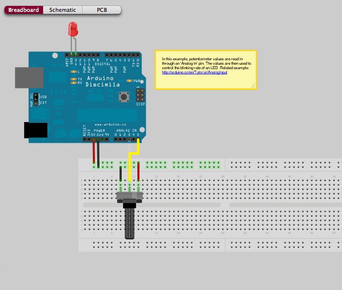
Attach the potentiometer onto a column on the breadboard so that all the legs are in the same column. Looking at the image below, the leftmost leg is connected to ground. For this project, you should connect the middle leg to analog pin 5. The rightmost leg should be connected to power.
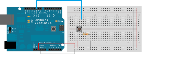
For the button, you want to position it on your breadboard so that the legs on opposite sides of the button spans a ditch (as shown in the digram). One leg should be wired to power; the other leg should be connected to the resistor(in the range of 1 kohm to 10 kohm) and digital pin 10. The resistor should be connected to ground. This image shows the correct wiring for a button connected to digital pin 10.
The Outputs: The LED Screen
-
Make sure that neither the Arduino nor the LED screen is connected to a power source - that is, neither to a USB cable, nor to a power converter.
-
Each pin on the Arduino is labeled - the digital pins go from pin 0 up to pin 13, the analog pins go from A0 to A5, as well as power pins marked GND (for ground) and 5V (5 volts). We will refer to these as pin 0, pin 1, … pin 13, pin A0, pin A1, … pin A5, and simply ground and power for GND and 5V.
-
The pins on the input connector of the LED screen are also labeled. The border of the board may obscure some of the labels, so we’ve recreated the diagram here:
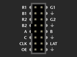
Here is (roughly) what the different pins do:
- The symbol that looks like a downward arrow stands for ground.
- The R1, G1, B1, R2, G2, B2 pins tell the screen what red, green, and blue values to display on the upper and lower half of the board respectively.
- The CLK (clock) pin tells the screen that new data has come in.
- The A, B, and C pins tell the screen which row is currently being described.
- The LAT (latch) pin tells the screen that it’s the end of the current set of data.
- The OE (output enable) pin tells the screen to move to the next row of LEDs.
-
On your ribbon cable, take a look at the connectors - one side of each connector has a bump, which fits into the corresponding gap in the Arduino input connector. If you lay the cable flat, then the pins on the two ends of the cable correspond like this:
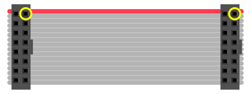
-
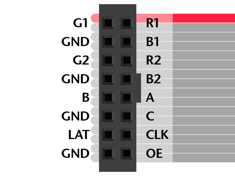
Plug one end of your ribbon cable into the input connector in your LED screen, then flip the screen back over and lay everything flat again. Because the LED screen is now flipped from when you were reading the pin labels, the pins are also flipped. That is, for the unplugged end of the cable, the corresponding labels would match those in Step 9 (NOTE: MAKE SURE THE RED STRIPE IS AT THE TOP LIKE IN THE IMAGE BELOW).
-
Just one more thing before we begin wiring. By convention, different colored wires are used for different things, so that it’s easier to separate them. The most common convention is to use red wires for power, and black wires for ground. In this project, we will also be using wires that represent the red, green, and blue values of LEDs. If you don’t have wires of these colors, don’t worry - you can still do the project, you’ll just have to keep track of the different wires more carefully.
-
Now we’re ready to start wiring. First, four of the input connector pins should be grounded (i.e., connected to ground). Since we only have three ground pins on the Arduino, we will need to use the breadboard. Take a wire - preferably black - and gently insert it into one of the ground pins on the Arduino. Take the other end and insert it into a hole on the breadboard next to one of the blue lines.
-
All the GND pins on the cable should be wired to other holes next to the same blue line. This connects those pins to the breadboard, which connects to ground on the Arduino.
-
The remaining wires go directly between the Arduino and the cable. The wirings, Arduino -> cable, are listed below. Make sure you do each one correctly; once everything is wired, it becomes much more difficult to check that a wire is connecting the right pins. The pin labels are included again for easy reference.
- 2 -> R1
- 3 -> G1
- 4 -> B1
- 5 -> R2
- 6 -> G2
- 7 -> B2
- 8 -> CLK
- 9 -> OE
- A0 -> A
- A1 -> B
- A2 -> C
- A3 -> LAT
-
Double check that everything is wired correctly. There should be two (2) wires between the Arduino and the breadboard, four (4) wires between the breadboard and the LED screen, and twelve (12) wires between the Arduino and the LED screen. (You will have more if you’ve wired the potentiometer and/or the button.)
-
Connect the Arduino to your computer with the USB cable.
-
Connect the LED screen to the power converter, and plug the power converter into a wall socket.
-
Wait for one minute, keeping an eye on the Arduino. The LEDs may remain off, or they may flicker depending on what is currently stored in the Arduino. Gently touch the chip on the Arduino (the large black rectangle in the middle), and make sure that it is not getting hot. If the Arduino gets hot, immediately unplug both the Arduino from your computer and the power converter from the wall socket. You probably wired your screen incorrect if this happens, and will need to check all your wires.
-
If after a minute everything still looks fine - no smoke, the Arduino is at room temperature - then your Arduino is ready to be programed!
-
You know you wired everything correctly if you run the plasma sample and it looks like this.
Software
WARNING: Do not start coding until you have wired your matrix properly and can test while you code.
See this page in the spec for Installing the Arduino IDE and creating a project with the starter files
Starter Files
You can download the starter files here.
All the code that you write for this project will be in the single distribution file. This includes not only the code for drawing the invaders and the player cannon, but also the code that determines whether the player has won or lost. The Arduino framework relies on two functions:
- setup() - This function is called at the very beginning when the Arduino starts. Any initialization code - including setting the Arduino to properly read from the potentiometer and the button, and to properly output to the LED screen - should be done in this function.
- loop() - This function is called repeatedly as the Arduino runs. This is where you will implement most of the game logic.
For convenience, we have outlined several classes for you. You are not required to use these classes, but they may help you get started. We have also given you several function headers. You are not required to use our functions if you don’t want to. You can create your own.
- The
Colorclass (not to be confused withCOLORbelow) is a wrapper aroundColor333(), so you don’t have to deal with RGB values directly. Severalconst Colors have already been defined for you, although of course you are welcome to define more colors. To use in thematrixfunctions, useColor::to_333(), eg.matrix.drawPixel(1, 1, GREEN.to_333());. - The
Invaderclass represents an invader. - The
Cannonballclass represents the cannonball. - The
Playerclass represents the player cannon. - The
Gameclass pulls everything together, and handles the logic of winning and losing, as well as the drawing of each game element.
The Arduino, Adafruit GFX, and RGB Matrix Panel libraries also provide several functions you may use. Some functions you may find useful include:
delay(int t)stops the execution of your program fortmilliseconds.millis()returns the number of milliseconds since your program started.pinMode(int pin, MODE)sets the argumentpinto take digital input - like a button. For this project,MODEshould always beINPUT.digitalRead(int pin)takes apin(like the one passed topinMode()) and returns eitherHIGHorLOW. For a button, this corresponds to the button being pressed and not being pressed respectively.analogRead(int pin)reads the value of the argumentpinand returns its value. This is used for analog inputs - like the potentiometer.
These functions, and many others, are all documented on the Arduino website.
In addition to Arduino functions, the Adafruit screen also has functions you can use. We have defined a global variable called matrix, which is how you control the LED screen. It has several member functions:
begin()initializes the screenColor333(int r, int g, int b)returns aCOLORwhere theintarguments are the red, green, and blue aspects of a color in the RGB model In this case, the argumentsr,g, andbmust be between 0 and 7 inclusive.drawPixel(int x, int y, COLOR)turns the pixel at (x, y) into the specified color. Since the screen is 32 LEDs wide by 16 LEDs high, this function requires0 <= x < 32and0 <= y < 16. IfCOLORis black (ie.r == g == b == 0), then the LED is turned off.fillScreen(COLOR)turns every pixel of the screen to the specifiedCOLOR.print(string s)switches the LEDs on screen to display the strings. This function can be used with the setCursor() function to print strings of text to the screen. The effects of this function is modified by several other functions; see below. print can also take an integer as a parameter:print(int num).setCursor(int x, int y)moves the “cursor” of the screen to the (x, y) location. This changes the effect ofprint().setTextColor(COLOR)sets the color of printed text toCOLOR. This changes the effect ofprint().setTextSize(int size)sets the size printed text. Asizeof 1 means the text will be 8 LEDs tall. This changes the effect ofprint().
For everywhere that we used COLOR above, we refer to the output of the function Color333(). You can learn more about the Adafruit libraries by looking at the .h files included with the distribution code.
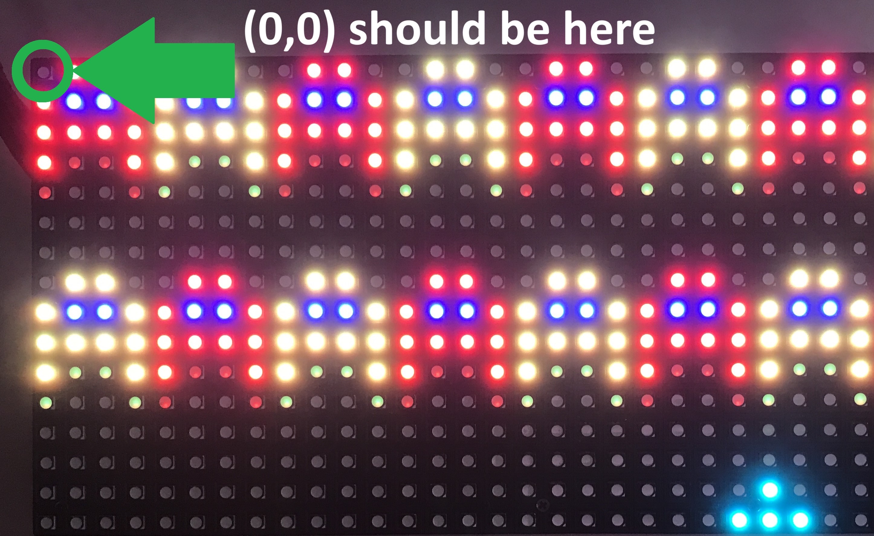
IMPORTANT: When creating your game, it is possible to make the pixel (0, 0) in either the upper-left hand corner or the bottom right. While you can make either orientation work, it is much less difficult to use functions like
matrix::printif the upper-left corner of the display is your (0, 0) coordinate.
Finally, you can use the Serial.print(string text) and Serial.println(string test) functions for debugging. This prints text to the Arduino IDE, much like cout prints to the console in Xcode or Visual Studios. Serial.print() does not insert an endl, while Serial.println() does. You can open the Serial monitor by clicking the top right of the Arduino IDE:
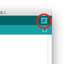
Be careful! If you use either function too many times in your code, your code could slow to a crawl.
Hints
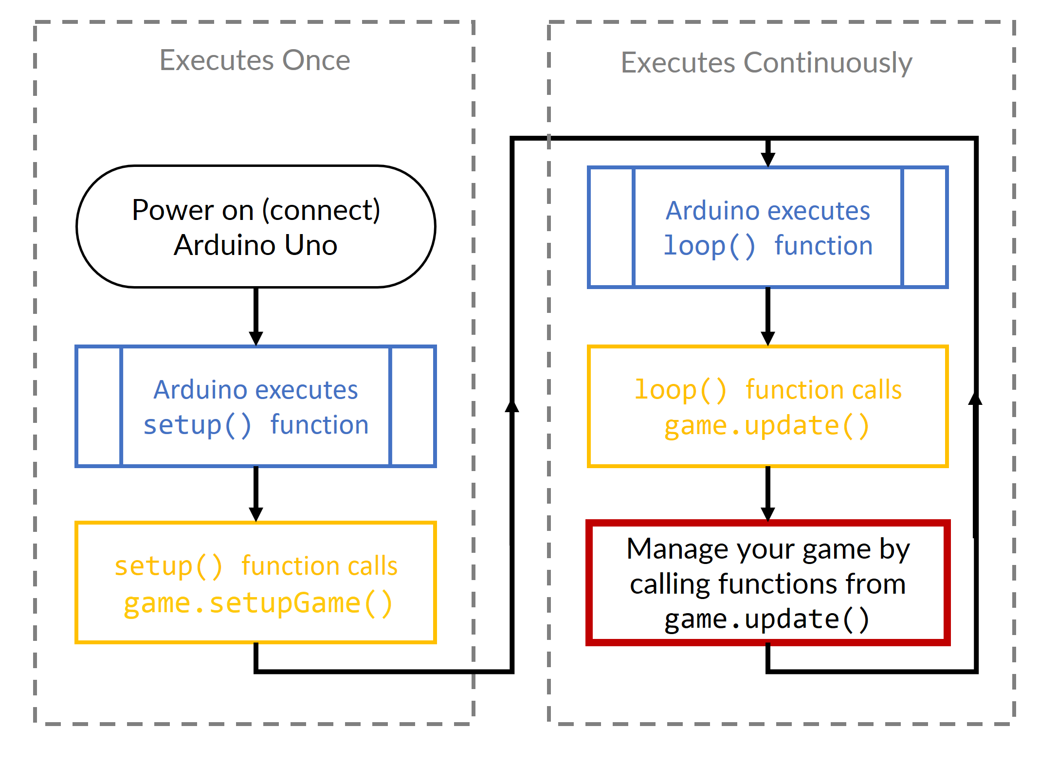
Arduino Uno
Before completing your game, it is helpful to understand the basic operation of the Arduino Uno.
Every sketch (program) for the Arduino contains two special functions: setup() (called setupGame() in our code) and loop().
The setupGame() is called once, when the sketch starts.
It’s a good place to do setup tasks like setting pin modes or initializing libraries.
The loop() function is called over and over and is heart of most sketches.
The Distribution Code already has the setupGame() and loop() functions defined for you.
Potentiometer
The potentiometer input is passed as an argument to the update() function of the Game class using the integer parameter potentiometer_value.
The position of the player cannon must correlate to the position of the potentiometer.
That is, when the potentiomter is rotated to the middle, the cannon should be in the middle of the LED screen.
As you rotate the potentiomter clockwise from center, the cannon will move to the right.
Any time you are not rotating the potentiomter, the cannon should not move accross the game screen.
You may find that your cannon has some small amount of jitter on the LED display. A simple method to help reduce this is called input smoothing.
General Game Rules
- Games start on level 1 (make sure to display level and lives before the game starts).
- Level 1 only has one row of invaders which move down at a timing of your choosing.
- If the player dies, the level they die on should restart.
- The player’s lives should decrement.
- Make sure to reprint level and (the new, updated) lives before the level starts again.
- The level should restart from the beginning with all invaders alive.
- Once the player successfully completes level 1, you should reprint level and lives before starting level 2.
- Level 2 has two rows of invaders.
- The bottom row should move at first (top row does not).
- Make sure that the bottom row does not move immediately after the game/level starts. They should move down after your set time increment once the game/level starts.
- The top row of invaders should start moving down once the entire bottom row is cleared.
- The bottom row should move at first (top row does not).
- Once the player successfully eliminates all invaders, they move onto level 3 which is the same as level 2 but has different strength invaders.
- Make sure to reprint level and lives before starting the level.
- The rest of the levels continue similar to levels 2 & 3 but with the invader strengths shown in the spec.
- Once the player runs out of lives, print “Game Over” and either leave “Game Over” on the screen or restart. If you choose to restart the game, the game should start at Level 1 and the player should have 3 lives again.
FAQ
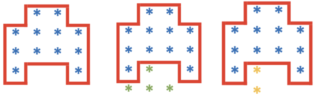
Q: What is the hitbox for an invader?
A: The cannonball and cannon should be able to go between the “legs” of the invader. The cannonball’s / cannon’s pixels should never be drawn on top of an invader. In the below images, the invader is drawn in blue, the cannon in green, and the cannonball in yellow, the hitbox is drawn in red (the colors may change for the actual implementation). To clarify, the image with the cannon should not cause the player to die. The player should die once the invader moves again or the player moves the cannon to the left. Similarly, the invader should not die in the image with the cannonball, but the invader should die once the invader / cannonball moves once more.
Q: How can I make levels 5 and up truly random? A: You will need to use the random seed function. Here is a link to the arduino website with more information.
Q: How fast should the invaders/player/cannonballs be? A: That is up to you! Just make sure that the game is playable (ie. the Invaders do not move down too fast) but it is also not too easy to beat
Q: I don’t like the colors given to the invaders/player/cannonballs. Can I change them? A: No, we want the core to be as close to the instructions we gave you as possible, so we know that you understand how to program the Arduino correctly. You can choose whichever colors you want to use for the reach!
Q: How many levels do I need? A: The game should continue on forever, you should be able to generate levels as long as the player hasn’t died 3 times.
Reach
For the Reach, your team may either signficantly extend the Core Invaders game, or create a new game or application of your design and vision. From the basic use of the Arduino microcontroller, there are many extensions for this project. The list of possible extensions to this project is limited only by your imagination. Note for the reach you must use an Arduino, i.e., you cannot use a Raspberry Pi or just a laptop.
NOTE: You are free to obtain and use new hardware in your Reach. Be sure to plan ahead; you will likely have to order all additional hardware over the internet and wait for it to arrive. We will provide extra buttons, potentiometers, resistors, wires, and breadboards as requested. We usually have a few Arduino Mega boards, and a few extra LED displays to loan - first come, first served. The LED displays included in the kit are only compatible with the Arduino Uno or Mega.
Here is a short list meant to inspire your team:
Extending your Invaders game:
- Adding sound to your games but this would not be a complete extension considering how simple it is. You would have to couple it with a few more ideas.
- Change the rules of the current game so that it has a more difficult implementation.
- Implement powerups that change the behavior of Invaders or the Player.
- Implement a scoring system and display score at times during and after the game.
- Create a boss battle(s) with unique new Invaders.
- Add another Player for multiplayer comptetitve or cooperative play
- Implement an AI to play the game for you.
- Add a menu system with game options.
- Add a welcome screen or animations during or after the game.
- Add new Player weapons or alternate fire modes.
- Make the Invaders march side to side as they march down the screen like the original Space Invaders
- Network your Arduino to a Python program on your laptop using Serial communication to display stats like score and Invader counts.
Creating a new game or application:
- Implement your own version of a classic arcade or other game: Frogger, Block breaker, Simon, a platform game like a Donkey Kong clone, Side-scrolling game like Super Mario, Snake, flappy bird, Google Chrome dinosaur game, or more.
-
Create a new application or game of your unqiue desing. Some examples that students have created before for the final project are unique rythm-based games and puzzle games.
- See the Reach grading rubric here for more details and guidance.
Submission and Grading
Submissions will occur via an autograder which is configured to only accept file submissions. You will create a sketch file starting from the distribution code. Your entire implementation will be in this one file. We will retrieve your file from your group repository on the due date. We are not grading the functions separately. We will run your game on a board and make sure everything that is specified happens correctly or points will be deducted. Do not just write your code without continuously testing it on the board. It will be exceptionally (impossibly?) hard to debug that way.
Submit your Core space_invaders.ino file to the autograder here Submit your Reach file to the autograder here Note that the autograder will be used to submit your work. Grading will be done by hand using the rubric linked below.
The final project grade is broken down as:
- 5 points: Team registration
- 5 points Showcase registration
- 50 points: Core
- 50 points: Reach
- 10 points: Team evaluations
- 10 points: Participation at Showcase on April 23
Grading Rubrics
- The rubric that staff will use to grade your Core is found here.
- Reach ideas, rubric, and grading guidlines can be found here.
Troubleshooting
If the Arduino IDE refuses to run on your compluter, you may need to use the Arduino Web Editor. Go back to the Arduino website and follow the instructions for the Ardunio Web Editor at the top of the page.
Project Help
Teaching staff are eager to help you succeed with the project. Here are some resources we will have in place:
- Office hours - for information about individual and group office hours check below.
- Final project tutorial session, scheduled for Sunday, March 29.
- Labs. Your lab session is a great way to find a partner and to learn what you need to complete the project.
- Tutorial videos on some of the tasks that students find challenging.
Office Hours
Office hours for the Arduino project are expected to be all in-person. Office hours can be in different locations, and may change. Check the calendar below to find the times and locations of each office hours block.
- The office hour queue will still be used. There is another queue named Arduino - please use this queue.
- Times and locations may change. Please check the calendar for planning.
Support Staff
Each project will have a dedicated group of staff to help your team be successful. Each staff member will support only a single project. Here are a list of the staff who will be supporting the project.
- Alyssa Locke
- Isabella Giaconi
- Leanne Cheng
- Xinyun Cao
- Ben Torralva
- Bill Arthur
Note: Depending on demand - teams are free to chose a project and it is impossible to predict demand precisely, the staff list may grow or shrink after the team registration deadline.